|
|
|||||||||||||||||||||||||||||||||||||||||||||||||||||||||||||||||||||||||||||||||||||
|
||||||||||||||||||||||||||||||||||||||||||||||||||||||||||||||||||||||||||||||||||||||||||||||||||||||||||||||||||||||||||||||||||||||||||||||||||||||||||||||||||||||||||||||||||||
|

 Introduction:
The Honda or Acura turns over but won't start in hot weather is a
Introduction:
The Honda or Acura turns over but won't start in hot weather is a | Quick Guide | |||
| Step A) | Look for the
symptoms by using your sense of
sight and sound. This can be confirmed by following the main relay basic troubleshooting flowchart below, usually performed while the car won't start. by using your sense of
sight and sound. This can be confirmed by following the main relay basic troubleshooting flowchart below, usually performed while the car won't start. |
||
| Step B) | Once confirmed that the main relay is dead, or if your car is over 8 years old, remove the main relay and remove the old solder from the weak joints and apply a fresh amount of rosin core solder. The instruction on how to do this can be found below. Or if you like other options see solutions.html | ||
| Step C) | Finally, install the main relay and test drive the car. The car should restart and idle on even the hottest day. | ||
For this repair project you will need a main relay and a set of proper tools:
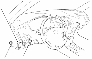
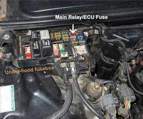
Where can I find the MainRelay?
 Honda/Acura
  Acura
Acura  Honda/Acura
 |
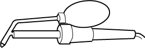
a 15-30 watt soldering iron (or 600F - 700F) * |
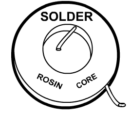 |
a Rosin core solder (Rosin is less corrosive) and |
 |
a solder wick (copper braid) (wicks/braids are bit tedious and usually wasteful on large jobs, but the wick is a good choice for this project.) or |
| a Desoldering pump (usually requires many attempts) or | |
 |
a Desoldering iron (simple to use, How to use, see step 1.) |
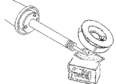
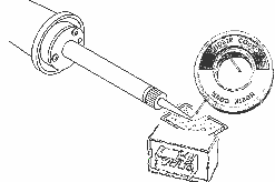
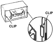
Start by carefully prying the main relay:
Clip----->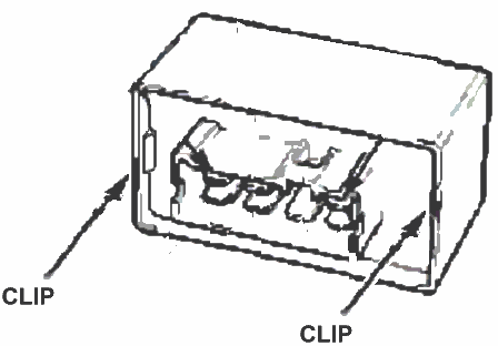 Stick a flat small flat screw driver in the crack.
| Separation Steps: | What to look for: | |
 |
 Fig. 12 |
|
- Stick a small flat head screw driver in between the wall flap (a clip) and the relay base.
- Do not go in too deep. Pry it open just slightly.
- While holding it still, use the same screw driver, pry the other side.
- While holding this side still (and cleared of the locking edge) pull the relay straight out, or forward.
- Installation is reverse of the procedure (Note: The main relay will only go in one way into the housing.)
Note: Do not stick the screw driver too deep inside. You may damage the relay's mechanical or electrical parts.
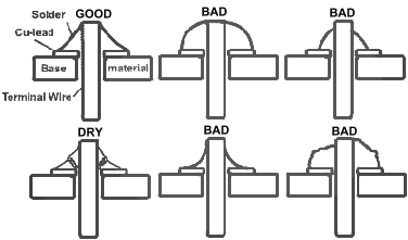 Fig. 4
The image above shows one good and several bad examples.
Examples:
The amount of solder (before) is too
little.
The joint (before) is a cold solder joint.
CAUTION: |
Try not to heat the joint too long with a 40 Watt or above soldering gun, because the copper traces on the circuit board may lift. |
Health warning: |
Do not over expose your lungs or eyes to the fumes. Wash hands with soap and water after handling the PCB's and leads. |

Desolder using a pump ![]() Desolder using a wick
Desolder using a wick ![]()
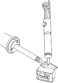
Desoldering using a desoldering iron. ↓

1.) Press and hold the air vacuum bulb. Apply the desoldering iron tip so that
the terminal penetrates within its orifice.
2.) When the solder liquefies, start gently to rotate the desoldering tip so
that the components terminal can be eased away from the sides.
3.) Release the air vacuum bulb just long enough to suck the solder.
4.) Once cleared of solder, begin soldering. Doing desodering and soldering one terminal at a time.
Note: If any solder remains are left on any terminal after attempting to desolder it, resolder it with fresh solder and repeat the desoldering process.
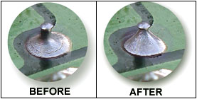
A clean removal should look like this:

- Parts could fall or drop into the main relay if more than two terminal are desoldered at once. Always desolder one terminal then go to step two below.
- The large terminals may require a 40 watt or higher soldering iron. The large terminals rarely fail and could be skipped.
![]() Heat the terminal and the copper trace with the iron tip while
applying the rosin core solder to the terminal.
Heat the terminal and the copper trace with the iron tip while
applying the rosin core solder to the terminal. ![]()

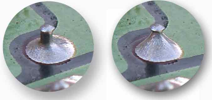
If you do have a joint which looks in need of rework don't be tempted to just reapply the iron. This is unlikely to succeed as the solder in place will have no flux in it, so the flow across the joint will be worse than when it was first made. Better to remove the solder, using a desoldering pump or copper braid, and make the joint again. The flux's job is to strip away all of the grease from the surfaces to be soldered, thus ensuring that the solder will flow properly. A concave should be formed with an angle of 40 and 70° from the horizontal.
Click here if you still have trouble creating a perfect joint.
A good solder job should look like this:

![]() (Optional) Clean with steel wool, inspect for imperfections then use a conformal coating
material. Conformal coating enhances performance, improves electrical stability
as well as accidental shorts and thermal shock. Their ingredients include
varnish, epoxy, parylene, polyurethane, silicone, acrylics, or lacquer. Coatings
are applied in a liquid form; when dry, they exhibit characteristics that
improve reliability. These characteristics are:
(Optional) Clean with steel wool, inspect for imperfections then use a conformal coating
material. Conformal coating enhances performance, improves electrical stability
as well as accidental shorts and thermal shock. Their ingredients include
varnish, epoxy, parylene, polyurethane, silicone, acrylics, or lacquer. Coatings
are applied in a liquid form; when dry, they exhibit characteristics that
improve reliability. These characteristics are:
-
Heat conductivity to carry heat away from components
-
Hardness and strength to support and protect components
-
Electrical insulation to preventing accidental shorts
-
Low moisture absorption
-
Prevents oxidation * tip: If your Honda digital clock currently works, now is a good time to protect it with conformal coating.
-
To remove the conformal coatings simply use acetone.
![]() Install onto the vehicle in a lower, practical location*,
easily accessible in the future. Your work is done.
Install onto the vehicle in a lower, practical location*,
easily accessible in the future. Your work is done.
 See all locations >>
Further explanations:
What causes the main relay to fail?
Short answer: The term 'cold solder joint' best decribes it. This develop over time with thermal cycling on parts that are not properly fastened and are essentially being held in by the solder alone. They may flex the connection due to vibration or thermal expansion and contraction. More info at FAQs page.
What is the solution to this problem?
The dry solder joints could have been easily eliminated if the solder quality is consistent and a concave should be formed with an angle of 40 and 70° from the horizontal. Four terminals and maybe more on the main relay are known to show signs of a cold solder joint.
Should I remove the old solder?
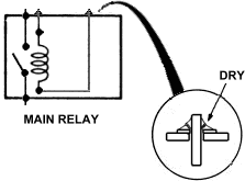
Yes. The old solder is of poor quality and damaged. Black areas on the joint indicate a "dry" joint. This is caused by dirt in the joint area and will result in an unacceptably high resistance. A soldered joint which is improperly made will be electrically noisy, unreliable and is likely to get worse in time. It could work initially and then cause the main relay to fail at a later date.
If it seems to take an unusually long time for the solder to spread, this is another sign of possible dirt and that the joint may potentially lead to a failure, usually in the form of stalling in traffic and won't start. It is hard to judge the quality of a solder based on the appearance of the joint because you cannot see how the joint had formed inside. So it is really a small price to pay to do it right the first time.
What happens if I just reheat or add additional solder to the joints?
The joint area will result in an unacceptably high resistance. Your symptom may return much earlier than a brand new main relay. Esitmated to be about a couple months. The car may stall in traffic and won't start. See our observations if you still want to skip the desoldering process.
How long will it last if I follow your instruction exactly?
7 to 10 years (California, or Southwest US climate.) Ours lasted about 14 years using generic solder. For good measure, we'd recommend that you come back to this page and do your fix again 7-8 years after you've done your first fix. There may be updates. Such as new claims that higher-temp silver solder may work better. We'll post it here. Also see "How can I make my relay last longer than 10 years?" on this page.
My Honda
does not like to start sometimes when it is hot out if I don't let the fuel pump
prime and then try to start it? Can this be a main relay problem?
Yes. But this can also be a sign of loss in fuel pressure overnight. Usually, the bad solder joint will make the main relay "lazy" and won't start until after a second or so. There are two ways to distinguish these signs. The "check engine light" that goes off the moment the car starts and the when the key is turn to ON, the fuel pump doesn't whirl right away is a sign of a bad relay. If the car starts only when the ignition switch is first cycled on and off several times then the fuel pressure may have been lost. This is most often due to a bad fuel pump, fuel pressure regulator, the fuel injector o-rings or the fuel injectors.
My check engine light is on (code 16) and it won't start. Is this caused by the main
relay?
Yes. If the ECU doesn't receive the power from the main relay, a
diagnostic code ![]() (fuel injectors) will show up on the diagnostic indicator after retrieving the
code. This is followed by the typical "no power to the fuel pump." A
no start with a steady on "check engine" light could also mean a
bad ECU power supply.
(fuel injectors) will show up on the diagnostic indicator after retrieving the
code. This is followed by the typical "no power to the fuel pump." A
no start with a steady on "check engine" light could also mean a
bad ECU power supply.
When I turn on the car the main relay starts clicking. I changed it out and still the same thing. What is causing it?
The main is getting low current. The result is a fast clicking relay. The current comes from the battery. The ECU then outputs the current on pin A7 on the ECU. The fix is to make sure the car battery is strong, connections tight and fully charged. Then make sure that the check engine light is not on and the ECU is properly grounded.

My 90-94 Accord doesn't shifts properly and the "S" (D4) light is blinking, can this caused by the main relay?
Yes. The transmission computer (TCU) realizes the main relay isn't supplying power for the TCU at startup. At which point the TCU shuts down.
This can happen when the ignition is ON and the ECU/TCU power supply from the main relay drops out momentarily. The dropout in power can be preceded by a sounds like relay(s) clattering in the dash for a few seconds. The clattering sound may also be the sound of transmission interlock system misbehaving, which may indicate a bad TCU. Or the clattering is the main relay itself, which can cause the TCU to go into a limp mode to protect itself. This could cause the transmission to stay in the wrong gears or won't shift at all. Read more about this under transmission.html#mainrelay.
What can make the main relay hot.
When a fuel pump demands more current, heat would be generated as a result of increase resistance in the fuel relay contact points. In this case the relays will act as heat sink. This is a sign that the contact is worn. The picture above explains why. When a relay contact becomes corrupt, caused by arcing or other means electrons will converge in poorly conductible space, creating a high resistance and heating up the relay. The relay wounded coil can also generate heat. Replace the relay if you suspect that the main relay is running too hot. Since heat poses a risk of another solder joint failure.
Sometimes a fuel pump may run endlessly because the relay contacts have welded together. Another term for this is resistance welding.
Tip: A brand new main relay will most likely use the same poor quality solder/application. It's recommended that you observe the solder application quality before installing the main relay. A brand new main relay will have a practical lifespan of 8-10 years, unless they have been updated.
How can I make my relay last longer than 10 years?
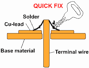
Some of the technique we've come up with to improve the relay's lifespan of up to 20+ years is to resistance weld the terminals. The 2nd alternative method is try the wire twist method - which is easy for DYI at home. Wire twist is a proven reliable method use in manufacturing.
A solid round copper wire is twisted with tension onto a terminal post. Often a post is rounded first. Some of the wire extends outward. All are then soldered normally. Since the wires extend outward, they aren't affected by expansion/contraction. Since the wires are held under tension onto the post, they can handle the expansion/contraction better than a rigid solder. Before doing the final soldering, a slight tap to sink the terminal posts to suspend the relay. This help to prevent the pull affect. That is when the terminal pulls or retracts into the circuit board when it contracts. We'll keep you posted as we do more research.
|
|
|||||||||||||||||||||||||||||||||||||||||||||||||||||||||||||||||||||||||||||||||||||
TROUBLESHOOTING THE MAIN RELAY |
You may read the FAQ for more basic troubleshooting, otherwise just follow this troubleshooting flow chart before performing the main relay bench test.
The main relay typically fails in three ways.
- One is when there is only 1 click after turning the key and the fuel pump won't run.
- The second is when the check engine light is steady on (no clicks) and the fuel pump won't run.
- The third, most uncommon, is when the check engine light goes on and off normally (click on and click off normally) and the fuel pump won't run. This symptom needs to be tested in order to rule out the possibility of a dead fuel pump or a bad power supply that is too low to run the fuel pump.
Basically, if the fuel pump is running the main relay is fine.
- If there are no clicks but the harness connector power supply is good, (how to test below) then the main relay is most often bad.
- The troubleshooting flowchart (which uses your senses) below is an accurate diagnose if your symptoms follow the flow of the chart.
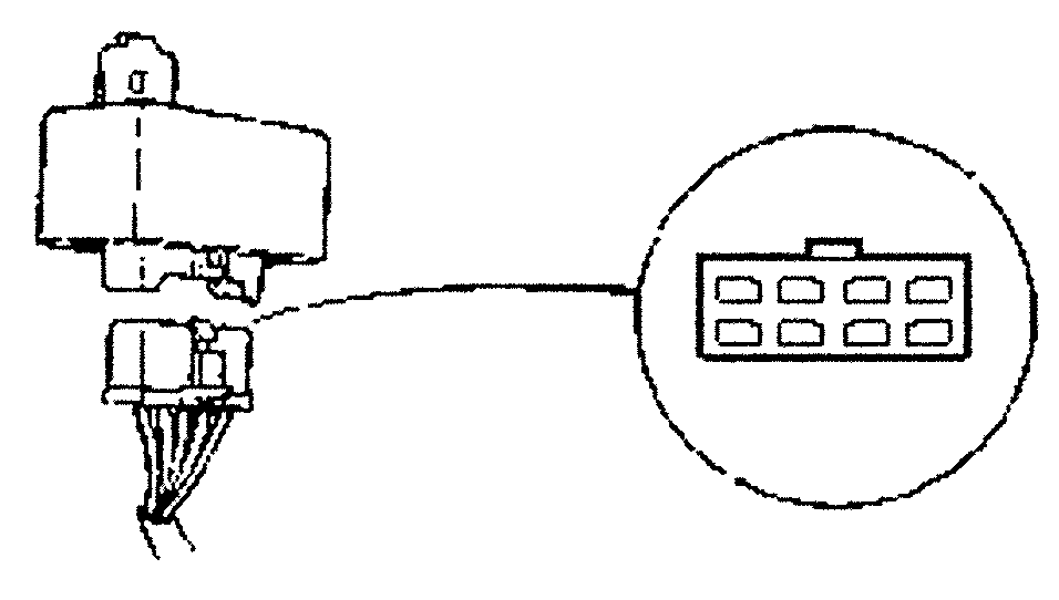
Problem: Won't start, the relay won't click and no fuel pump sound. Solution: Follow the steps below to check the power supply.
Note: With the relay connected and the key turn on, the check engine light must go on then off after two seconds in order for the fuel pump to run
for the initial 2 seconds after the key is turned on. Another words; no ECU, no fuel pump priming.
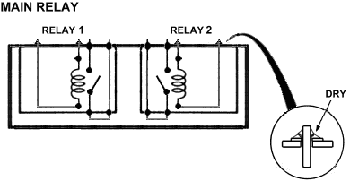
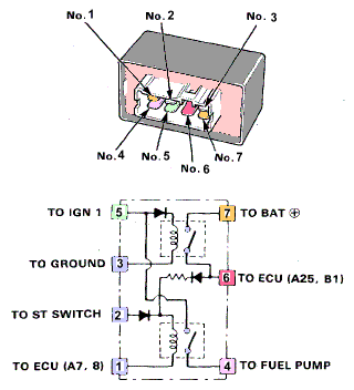
Main Relay bench test: Introduction: Basically, the most common main relay circuit comes in two flavors. Notice the differences between the two identical looking relay side by side below. Now notice that only terminal 4 and 6 are swapped. This means that the troubleshooting procedure below should work for both types of main relay. The main relay usually fails intermittently. That means that by the time you have it ready on the bench, the problem have probably disappeared. You have three choices when the car won't start:
Main relay bypass: Bypassing the main relay to get the car running. A few have asked how to bypass the main relay. Simply remove the main relay from the harness connector and short the three terminals on the wire harness connector together and turn the ignition switch to start. Here are the terminals.
First generation relay: Battery(1) fuel pump(7) and
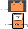
ECU/injectors (3). WARNING: Do not jump the battery power (+) to terminal 8 (or terminal 1 for the 95-97 Civic) on the wire harness connector or there may be an internal short or ECU damage. The following test is for most Accords, mainly for the Accord 88-94 and for the Acura or for most generic main relays. Step 1: Attach the battery positive terminal to the No.4 terminal (for the Accord) or No.6 (for the Acura) and the battery negative to the No.8 terminal of the main relay. Then check for continuity between the No.5 terminal and No.7 terminal of the main relay.
Step 2: Attach the battery positive terminal to the No.5 terminal and the battery negative to the No.2 terminal of the main relay. Then check for continuity between the No.1 terminal and No.3 terminal of the main relay.
Step 3: Attach the battery positive terminal to the No.3 terminal and the battery negative to the No.8 terminal of the main relay. Then check for continuity between the No.5 terminal and No.7 terminal of the main relay.
For the Civic 95-97. Step 1: Attach the battery positive terminal to the No.2 and the battery negative to the No.1 terminal of the main relay. Then check for continuity between the No.5 terminal and No.4 terminal of the main relay.
Step 2: Attach the battery positive terminal to the No.5 terminal and the battery negative to the No.3 terminal of the main relay. Then check for continuity between the No.7 terminal and No.6 terminal of the main relay.
Step 3: Attach the battery positive terminal to the No.6 terminal and the battery negative to the No.1 terminal of the main relay. Then check for continuity between the No.5 terminal and No.4 terminal of the main relay.
Note: This relay is the same version as the Acura, but differs only by the printing. This would mean that these species of relay are manufactured in two formats.
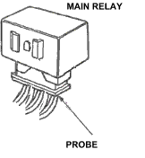
Main Relay in Circuit Test
Main Relay Terminals: For most Accords: While still connected to the vehicle check that:
Main Relay Acura Legend, TL, and RL Bench Test. Step 1: Attach the battery positive terminal to the No.4 terminal and the battery negative to the No.8 terminal of the main relay. Then check for continuity between the No.5 terminal and No.7 terminal of the main relay.
Step 2: Attach the battery positive terminal to the No.6 terminal and the battery negative to the No.2 terminal of the main relay. Then check for continuity between the No.1 terminal and No.3 terminal of the main relay.
Step 3: Attach the battery positive terminal to the No.3 terminal and the battery negative to the No.8 terminal of the main relay. Then check for continuity between the No.5 terminal and No.7 terminal of the main relay.
Factory unabridged 95-97 Civic main relay test . 
| ||||||||||||||||||||||||||||||||||||||||||||||||||||||||||||||||||||||||||||||||||||||||||||||||||||||||||||||||||||||||||||||||||||||||||||||||||||||||||||||||||||||||||||||||||||


