
This page records any new changes for returning viewers

TCU/TCM Fix Tutorial How to fix your TCM and save $500US, then donate the money you saved to charities that will self empower others.
Problem: Won't start, the relay won't click and no fuel pump sound.
- Connect your black probe of your multimeter to terminal 2. Connect your
red probe to terminal 1. There should be battery voltage. If not then check
the ECU fuse.

- Turn the ignition switch to ON. Connect your black probe of your multimeter to terminal 2. Connect your red probe to terminal 5. There should be battery voltage. If not then check the fuse or the ignition switch.
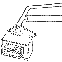
A few images are added in the main relay replacment page. See
http://techauto.awardspace.com/mainrelaydefine.html
A few images are added in order to get an insight into the problem and to better prepare yourself.

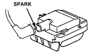
Above: The end result of arcing. How to replace the ignition switch or troubleshoot (Honda, Acura)
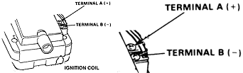
Ever wonder why there isn't an easy way to check the condition of your ignition switch quickly and easily. The answer is because it's so easy they don't want you to know. Today, a diagnose can run you $89 an hour. They don't want you to know the secret. Well, the secret is out. You can check the condition of your ignition switch by checking for power at the coil. The voltage that you see can determine the condition of the ignition switch. If the voltage is at 12V or higher, then that is sign of a good ignition switch. If it's 12V or under, it is an aging switch, but doesn't necessarily mean it's a defective switch. Begin by checking for power at the ignition coil (terminal A) with the ignition switched to ON. There should be battery voltage.
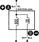

For the 88-89 Accord coil, see this [image.] For
the civic coil see this [image].
If there is no power then check the ignition fuse (most often labeled IG...) in the engine bay fuse box. If the fuse is fine then continue below.
How to replace the ignition switch or troubleshoot (Honda, Acura)
Can be found here. mainrelay.html#Troubleshoot3
|
|
|||||||
|
|
|
|
|||||
|
|
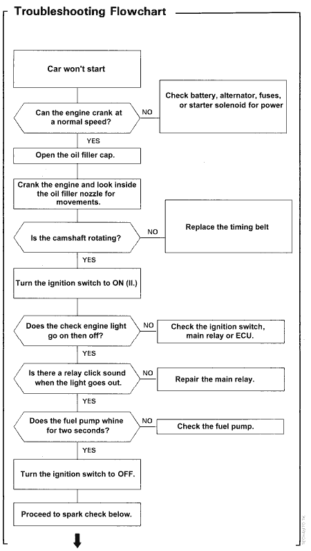
Car Won't Start |
|
Main relay troubleshooting for most Honda/Acura PGM-FI relay and harness |
|
|||
|
|
|
||||||
|
|
|
||||||
|
|
|
||||||
|
|
|
|
|||||
|
|
|
|
|||||
|
|
Turn the ignition switch to ON. |
|
|
||||
|
|
|||||||
|
|
|
||||||
|
|
|
||||||
|
|
|
|
|||||
|
|
|
|
|||||
|
|
Does the check engine light go on then off? |
|
|
The ignition switch and ECU is okay. |
|
|
|
|
|
|
||||||
|
|
|
||||||
|
|
|
||||||
|
|
|
|
|||||
|
|
|
|
|||||
|
|
Is there a relay click when the check engine light is on? |
|
|
Main relay is dead. |
|
|
|
|
|
|
||||||
|
|
|
||||||
|
|
|
||||||
|
|
|
|
|||||
|
|
|
|
|||||
|
|
Is there a relay click when the check engine light is off? |
|
|
Main relay is dead. |
|
|
|
|
|
|
||||||
|
|
|
||||||
|
|
|
||||||
|
|
|
|
|||||
|
|
|
|
|||||
|
|
Does the fuel pump whirl for 2 seconds when the check engine light is on? |
|
|
Fuel pump may be dead. Check the fuel pump. |
|
|
|
|
|
|
||||||
|
|
|
||||||
|
|
|
||||||
|
|
|
|
|||||
|
|
|
|
|||||
|
|
Main relay is OK. Turn ignition off. |
|
|
||||
|
|
|||||||
|
|
|
||||||
|
|
|
||||||
|
|
|
|
|||||
|
|
|
|
|||||
|
|
More troubleshooting can be found at mainrelay#Trbsh3 |
|
|
||||
|
|
|||||||
|
|
|
||||||
|
|
|||||||

Could this happen to you. Rarely would we find our door jams shut and can't get in or get out. You could remove the door panel and poke around or you could drill a single hole painlessly and the door pops open. Or... maybe, you'll need more than just a single hole. Here's a step by step guide to solving the problem . See http://techauto.awardspace.com/doorproblem/index.html#latch.
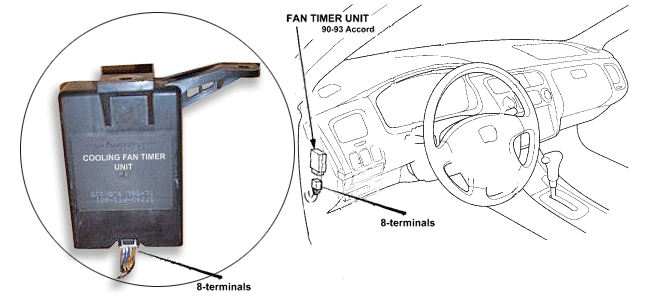 How to replace the fan timer.

How to prevent your plastic radiator from cracking using epoxy, a couple steel plates or zip ties.


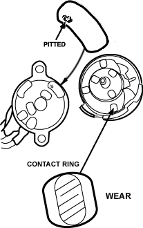
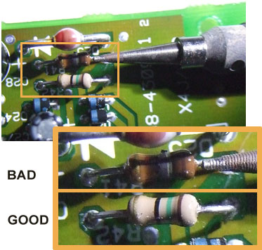
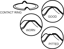
Thanks to Steve for drawing this picture. This helps us see why the ignition switch contacts are worn. A real image would work but then photographic images can't be printed.
Main Relay Technical details
What is the main relay?
The main relay (which consists of two relays that are remotely operated as a switch) is a device that opens or closes under control of another device usually the ignition switch or ECU. The main relay opens and closes the fuel pump, the fuel injection and ECU.
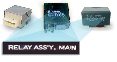
How do I identify the main relay?
Look for RELAY ASS'Y. MAIN
Technical Details

1.) Press the vacuum pump
push-bulb. Apply the desoldering iron tip so that the
terminal penetrates within its
orifice.
2.) When the solder liquefies, start gently to
rotate the desoldering tip so that the
component’s terminal can be eased away
from the sides.
3.) Release the vacuum pump
push-bulb just long enough to suck
the solder.
Note: If any solder remains are left on any terminal after attempting to desolder it, resolder it with fresh solder and repeat the desoldering process.
More at mainrelay solder page
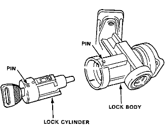
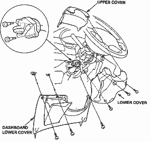
Replacing key cylinder on 86-89 Accord.
Note: These steps are not for the novices. They are here for our technical member's reference since it's one of the FAQ. If you don't understand then post a comment.
Steps:
- Turn switch to ON (I) pin button down. Pull cylinder out.
- Please go to igniton switch to read more...
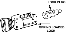
Removing the tumbler from the cylinder
- To eject the tumbler from the cylinder.
- Remove spring loaded key lock cover on cylinder.
- Stick key inside. Twist key to opposing direction.
- Push cylinder out from the other end.
Removing the bolt from the steering column.
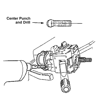
- Center punch the bolt at 3'O clock.
- Slightly angle the center punch and punch the bolt out counterclockwise.
More...
View at http://techauto.awardspace.com/ignitionswitch.html#key
 problem/solution
location http://techauto.awardspace.com/faq#carb
Door won't open due to latch failure. See
http://techauto.awardspace.com/doorproblem
 View
View
View this
 |
|
||||||||||||||||
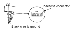
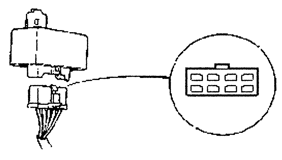
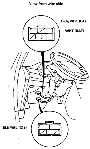
Troubleshooting at the harness:
Steps:
- Follow the harness from ignition switch to the fuse box. Disconnect the ignition switch wire harness connector from the fuse box.
- Touch the probe of the a DMM to WHT.
- Touch the other probe of the a DMM to BLK/YL. There should be continuity when the ignition is switch to "ON."
- Remove the probe from BLK/YL (Do not remove the probe of the a DMM to WHT.)
- Touch the other probe of the a DMM to BLK/WHT. There should be continuity when the ignition is switch to "START."
- If you do not find the continuity as specified replace the ignition switch.
- If you do not find the wire colors as specified on your ignition switch, stop here and consult your service manual.
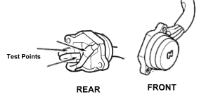
Troubleshooting at the switch:
Tool required: test light

![]()
Steps:
- Connect the negative end of the a DMM (test light okay) to ground (any metal part of the steering column) and the other to WHT. There should be battery voltage.
- Connect the negative end of the a DMM to ground (any metal part of the steering column) and the other to BLK/YL. There should be battery voltage when the ignition is switch to "ON."
- Connect the negative end of the a DMM to ground (any metal part of the steering column) and the other to BLK/WHT. There should battery voltage when the ignition is switch to "START."
- If you do not find the continuity as specified replace the ignition switch.
- If you do not find the wire colors as specified on your ignition switch, stop here and consult your service manual.
Note: Puncturing the wires to check for voltage is not recommended since the internal wires may exposed to the environment. With every puncture the wire should be sealed with RTV silicone. Avoid damaging the female connector terminals, do not insert your probe deep into the female connector, instead lightly touch the terminal's copper surface.
Note: This diagnose does not cover accessories such as the blower motor and etc. This is because they are not mission critical and are simply luxury items which requires a unique set of procedures beyond the scope of this page.
Location ignition switch
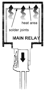 Heat rises to the top
where the circuit board sits. The joint can fail and won't show the usual visible
signs of crack.
If your joints are properly soldered then the heat won't affect it. However, if
you believe heat is the problem then you can mount the main relay upside down.
A leaking roof can contaminate the relay...
Heat rises to the top
where the circuit board sits. The joint can fail and won't show the usual visible
signs of crack.
If your joints are properly soldered then the heat won't affect it. However, if
you believe heat is the problem then you can mount the main relay upside down.
A leaking roof can contaminate the relay...
Location heat and holes
Main relay reliability test
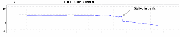
Overview: In this experiment a bad main relay used to recreate an early failure. This relay known to develop a bit of a heat under normal operating conditions. Normal relays won't behave this way.
In this experiment we will run the vehicle until it stalls or won't start under an extreme condition of heat and abuse. As you can see after several months the relay will begin to fail as this graphs records the event...
Location http://techauto.awardspace.com/index.html?content=mainrelaytest
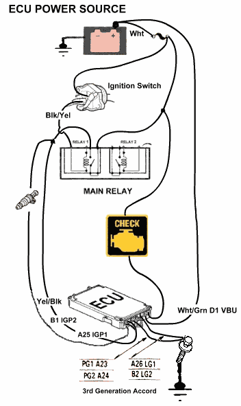 Overview: When the "check engine" light is constantly on and
won't start then this is a symptom of no power or no direct connection
between the ECU and it's feed sensors.
Overview: When the "check engine" light is constantly on and
won't start then this is a symptom of no power or no direct connection
between the ECU and it's feed sensors.
Step1. Check all ECU grounds. The ground is bolted to the frame. Follow
a couple black wires from the ECU to a bolt. Make sure they are secure.
Step 2. Check the ECU connection at or near your battery post. The ECU power supply doesn't have a fuse. Then check the power input on the ECU ports.
Step 3. Check the main relay. Make sure Yellow/Blue and Yellow/Blak has battery power...
Location http://techauto.awardspace.com/ecu.html
Cache of factory main relay test for 95-97 Civic.