Main relay reliability test ( lasting 14 years max, California region)
Overview: In this experiment a bad main relay is used to recreate an early failure to prove that desoldering is required. The bad relay is used to help speed up the experiment. Normal relays won't behave this way.
In this experiment we will run the vehicle until the car stalls or won't start under an extreme condition of heat and abuse. As you can see several months later the relay will fail as this graph records the event.
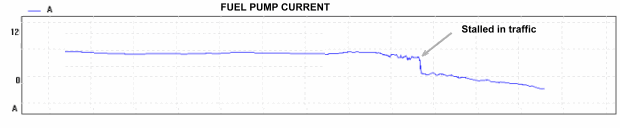
This graph shows a length of a few seconds and how the current behaves before the vehicle stalls in traffic. Usually the car won't start unless the vehicle cools down or a key pressed against the solder joint or joints.
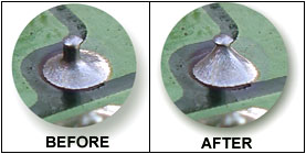
The chart below show how different methods and solder materials are used in this experiment. Notice that none of the mainrelay use plain solder. They are all rosin core solder. A few websites are misleading when all you need to do is to reheat the solder joints without flux and new solder.
Test based on solder application.
| Type of solder | Desolder | Solder Amount* |
Num of days before failure |
Stalled in traffic |
Solder Iron/ Watts | Joint areas redone |
| 40/60 Normal Rosin core | No | Little | about 90 | Yes | Control temp/600C | Small terminals only* |
| High silver Rosin core | No | large | about 120 | Yes | Control temp/600C | Small terminals only |
| High silver Rosin core | Yes | correct | about 1.5 years | No, but failed to start in one occasion for 2 seconds | Control temp/600C | Small terminals only |
| 40/60 Normal Rosin core | Yes | correct | 2 year and counting | No | Control temp/600C | Small terminals only |
* Small terminals only = this is part of the circuit board where the small terminals characterized by the small amount of solder used. This is not the section where globs of solders are used located on the larger terminals on the edges of the circuit boards. These terminals don't usually fail.
*Solder Amount = how the solder is applied. Little means the same amount similar to the factory amount. Large meaning globs. Correct meaning 40-70 degrees from horizontal.
How the experiment is conducted. A logic electrical configuration is set up to automatically kick in the backup relay in an event the test subject main relay fails. A warning is indicated for the driver. Then the relay is check to see which joint had failed simply by pressing the tip of the car key on the joint and attempt to start the car. If the car starts then that joint is logged. This has to be done quickly otherwise the joints will cool off. The failed joints are usually in or near the center of the circuit board.
Conclusion:
-
Desolder your joints.
-
Desolder and resolder all the joints that doesn't look like they have enough solder.
-
Handle the solder gun swiftly using the correct temperature (not too low.)
-
Use quality 40/60 rosin core solder or use quality solder and rosin paste.
-
Avoid too long iron exposure on the terminal and rosin core solder or avoid reapplying the solder iron to the solder joints once the solder has finished and solidified.
-
Show completeness with your work and wipe away any remaining flux and debris (which can aid in a diagnose.)
Remember that other factors which affect the reliablity isn't shown here. Such as how the relay is not suspended or coushioned during soldering. This prevents the terminals from shifting during expansion contraction.
Add your comments, suggest corrections or clarifications. Thanks.